The morning shift at a rigid box plant often starts with the same ritual: a stack of 2.5 mm greyboard waits beside the machine, the operator tightens the plate, and the first dozen sheets come out clean. By mid-morning, edges begin to feather. Pressure drifts, so speeds are dialled back. A job that was quoted at 1,200 sheets per hour settles around 800. The waste bin fills with rejected lids.
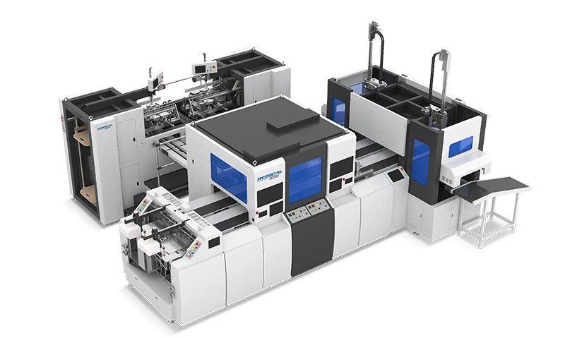
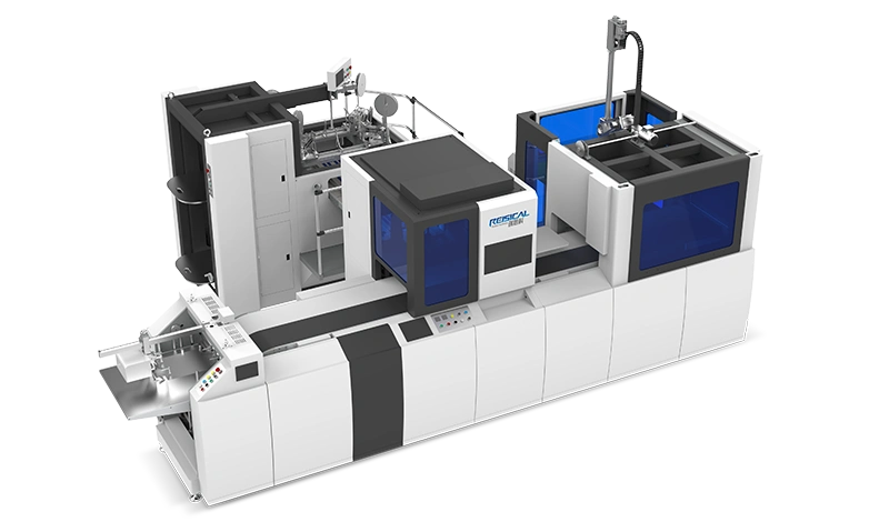
When thick substrates – heavy chipboard, corrugated fibreboard, laminated book covers – move through the converting line, the challenge is rarely about pure force. The real bottleneck is stability over a full shift. Every time an operator pauses to re‑tighten a chase, adjust stripper pins, or clear jammed scrap, the average cutting speed tumbles. In many cases, the root cause isn’t simply the machine’s power rating, but how well the entire cutting system is tuned for dense, multi‑layered sheets. Shops that treat the process as a series of interdependent variables – tooling, pressure mapping, material conditioning, and material handling – consistently outperform those that just buy more tonnage. And that’s precisely where a purpose‑engineered configuration makes a measurable difference: converters working with consistently dense packaging stock can systems specifically integrated for thick substrate processing to avoid the trap of retrofitting lighter equipment.
Why Thick Materials Are Unforgiving
Standard die cutting wisdom tends to assume a uniform cutting stick and a reasonably homogenous sheet. Thick packaging materials break those assumptions. Three factors interact in ways that degrade stability:
Compression recovery. A dense chipboard sheet compresses under the cutting rule before it fractures. If the press frame deflects even slightly, the rule doesn’t penetrate completely on every stroke. The result is partial cuts that tear instead of shear, leaving hairy edges and forcing a speed reduction.
Knife side‑load. When a rule strikes 3 mm of laminated board, lateral forces spike. Standard chase‑locking systems can micro‑shift, altering the shut‑height across the platen. Within 500 impressions, the operator notices inconsistent pressure zones – usually at the trailing edge of the sheet.
Scrap adhesion. Thick material creates heavy waste skeletons that don’t strip as freely as 0.5 mm cartonboard. Without dedicated stripping gear and properly timed air bursts, the waste rides back into the next cycle, causing double‑hits and tool damage.
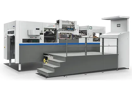
Addressing these three factors turns a capricious process into a predictable one. A heavy duty die cutting machine may provide the structural mass to resist deflection, but mass alone doesn’t guarantee efficiency. The difference lies in how the system manages dynamic forces at production tempo.
Pressure Mapping: From “Feel” to Data
Many operators set platen pressure by tapping a tissue paper or checking a crush mark. For thin stock, that artisanal touch works. For thick materials, it is the fast track to inconsistent die life and oscillating output.
A more reliable approach uses pressure‑sensitive film placed between the cutting plate and the die board. After one impression, you get a colour‑density map showing exactly where the load concentrates. A well‑adjusted setup targeting 1.2 mm‑thick greyboard might show 85–90% contact uniformity. On thick stock, anything below 80% usually means the corners of the die are working overtime while the centre is starved. The fix is typically a combination of kiss‑cut adjustments on the make‑ready sheet and replacing worn platen springs.
Translating that map into a maintenance checklist yields immediate gains. One book‑cover converter we worked with reduced rule breakage by 40% simply by mapping platen pressure every Monday morning instead of “when things sounded wrong”. This shift from reactive to predictive behaviour is what separates a speed‑focused shop from an efficiency‑focused one. When you have verified that the platen surface remains parallel to within ±0.03 mm under full load, you can confidently run closer to the machine’s rated stroke rate. For shops that need to maintain that level of precision across multiple substrate calipers, it’s worth reviewing pressure control solutions for rigid materials that incorporate in‑built hydraulic or servo‑driven compensation.
Tooling Choices That Scale With Thickness
Blade geometry matters more than horsepower. For boards above 1.5 mm, the rule should shift from a standard 23.8 mm height to a stronger 32 mm profile with a double‑bevel edge. The bevel angle matters: 52–54° for fibrous chipboard, 48–50° for laminated or plastic‑coated board. Wrong bevel and you’re trading tonnes of force for friction heat, which degrades the adhesive that holds the blade in the die board.
Equally critical is the ejection rubber. Thick material needs taller, denser ejection strips – 70–80 Shore A – placed as close as 3 mm from the cutting rule. If the rubber sits too far back, the board bows and the cut shifts. If it’s too soft, the sheet won’t release from the rule in time, forcing the operator to slow the press.
A quick rule of thumb: for every 0.5 mm increase in board thickness, ejection rubber height should increase by 1.5 mm, and its compression path should be re‑verified with a depth gauge. Documenting these settings, rather than eyeballing them, builds a repeatable recipe book. Repeatability is the bedrock of steady output.
Material Conditioning – The Overlooked Lever
Paper‑based packaging materials absorb moisture from ambient air. A 2 mm greyboard that contains 7% moisture cuts differently from the same board at 9%. The difference can be 10–15% in cutting force – enough to push a borderline setup into failure territory. Shops that operate in humid climates without conditioning often blame the tooling when the real culprit is hygroscopic expansion.
The minimum practical step is to let stock acclimate in the production area for 48–72 hours, wrapped but not sealed, with a datalogger tracking temperature and humidity. If the board arrives cold from a warehouse in winter, immediate cutting will generate condensation on the surface and cause fibre tear. Some converters add a simple infrared pre‑warming stage before the feeder; a 3 °C rise in board surface temperature can lower the cutting resistance by a measurable margin.
When conditioning becomes part of the standard operating procedure, the machine stops getting blamed for seasonal variation. The most efficient operations I’ve audited treat the die‑cutting department like a controlled environment zone – not a full cleanroom, but a space where temperature stays between 18–25 °C and relative humidity remains 45–55%. This alone extends tool life and stabilises registration.
Balancing Speed and Waste Stripping
Nothing erodes thick‑material efficiency like a stripping station that can’t keep pace. The heavier the waste skeleton, the more momentum it carries. If the stripping pins are mis‑timed by even a few degrees of crankshaft rotation, the skeleton tears and leaves partial waste in the die. Then the operator has to stop, clear the jam, restart – losing 3–5 minutes per incident.
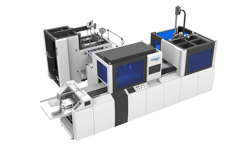
A modern solution is to pair the upper stripping frame with a dedicated lower stripping board that uses contoured channels to guide waste away. Some systems now incorporate pneumatic waste‑diversion flaps that redirect the skeleton without touching the finished part. This becomes essential when running nested layouts on a 1,200 mm × 900 mm sheet where the waste skeleton can weigh several hundred grams.
To see how fully coordinated stripping and material handling can eliminate the largest source of unscheduled stoppages, you can explore automated stripping and feeding configurations that take the trial‑and‑error out of the process.
Building a Sustainable Efficiency Playbook
Steady cutting efficiency doesn’t come from a single upgrade. It comes from documenting cause‑and‑effect and building a standard playbook. One durable approach is to create a one‑pager for each material grade that lists:
-
Recommended bevel angle and blade height
-
Target platen pressure map threshold
-
Ejection rubber specification and spacing
-
Minimum conditioning time and climate window
-
Maximum strokes per resharpening cycle
This playbook turns tribal knowledge into a company asset. Over a 12‑month period, converters who adopt such documentation typically see a 15–25% reduction in makeready time and a noticeable drop in tooling spend. Furthermore, when a heavy duty die cutting machine is operated within those documented boundaries, its core mechanical components – bearings, toggle linkages, platen guides – wear predictably, enabling condition‑based maintenance rather than reactive repairs. That is the definition of stability: a process that degrades gracefully and gives you warning, instead of failing by surprise on a rush order.
If you’re aiming for this level of predictability across mixed batches of dense packaging materials, having a line that was calibrated for these exact demands from the start shortens the learning curve dramatically. Ruisike, for instance, engineers its converting modules around the real‑world variability of rigid box board, laminated stock and heavy display board. Rather than forcing a universal‑fit machine to adapt, you can begin with a system that already reflects the tolerances and handling specifics thick materials require. Take a moment to browse Ruisike’s converting lines for thick packaging and see how a pre‑integrated configuration can move you from constant troubleshooting to repeatable, shift‑over‑shift consistency.
Disclaimer: The technical suggestions in this article are based on general industry practice and publicly available converting science (e.g. TAPPI T 826, ISO 12647‑6). Machine specifications and capabilities vary; always consult the equipment manufacturer’s documentation for specific settings and safety guidelines.